Operation GRAZE
Designing and building a tracked, solar-assisted rover to tow a supplement trailer between paddocks.
- Mechanical & Structures Lead
- Prototyping
- Monash Automation
- 24 V tracked skid-steer base, roof-mounted solar
- CAD / 3D printing / Fabrication / Simulation
- Robotics / Mechanical
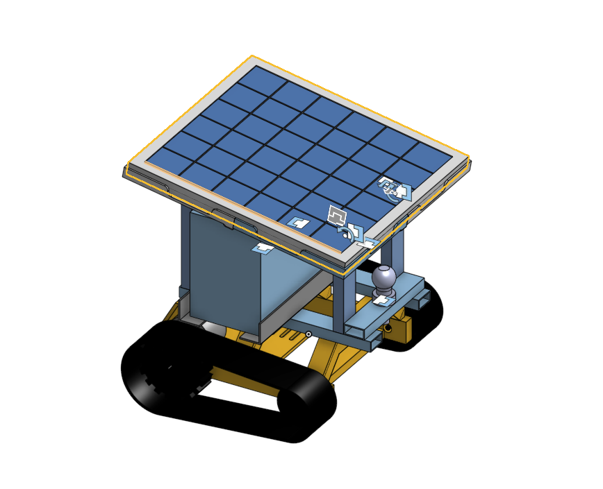
The latest CAD model: tracked base, enclosure, tow hitch and roof-mounted solar panel.
Why we built it
Moving supplementary feed with a herd during rotational grazing takes a person, a vehicle and repeated trips across a property. Our team set out to test whether a small autonomous rover could take on the transport part of that job. GRAZE is a student-built proof of concept, not a finished farm product: it needs to tow a trailer, follow a route and stop safely before the broader question of farm deployment can be answered.
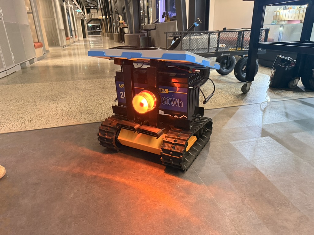
The rover uses a tracked, skid-steer base, a 24 V electrical system and a roof-mounted solar panel. Its two tracks are driven independently. The team has demonstrated a programmed loop between GPS waypoints while towing a trailer. The project remains in development, with performance on changing terrain and longer-term reliability still to be tested.
My part of the project
I led the mechanical and structural work: overall rover layout, chassis integration, CAD, component mounts, packaging, protection from water and vibration, and fabrication. I worked through stress and strain, traction and towing calculations, centre of mass, and where to position components so the trailer and drive forces would not create avoidable pitching problems. I also helped build simulations to explore towing capability before we tested the physical machine.
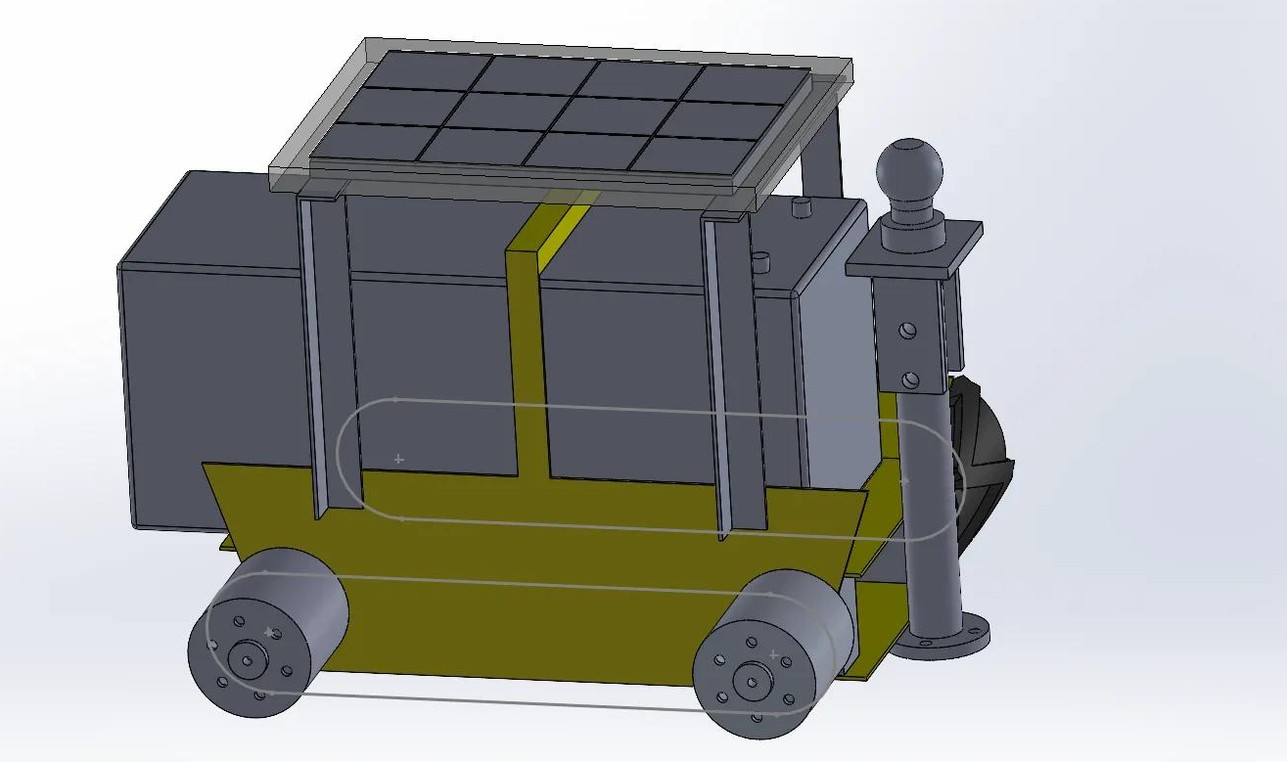
The base arrived without the documentation needed to design around it. I measured the physical frame and reconstructed it as a close-to-one-to-one CAD assembly. This was the hardest modelling task in the project: motor locations, arches, available mounting space and insertion paths all mattered, and small errors became real fit problems once we printed parts.
I specified mechanical dimensions and motor electrical requirements, proposed a stacked ESP and companion-controller arrangement, and took part in test planning, assembly, wiring and soldering. Our electrical leads owned the detailed power architecture, solar component selection, wiring diagrams, isolator and emergency-stop implementation. The navigation and sensing work was also a team effort.
Making the hardware fit
The electronics enclosures were a useful lesson in the difference between fitting in a space and being installable in that space. A box could clear the frame in CAD but catch on an arch while being lowered into position. Other prints revealed magnet recesses that were too tight. I revised the geometry, clearances and print designs through repeated physical fit checks.
The solar mounts changed for a different reason. We initially intended to machine them, but the available stock and budget pushed us toward 3D printing. A sharp, unfilleted corner then became a failure point. That changed how I looked at printed structural parts: the material choice, geometry and manufacturing process have to be considered together.
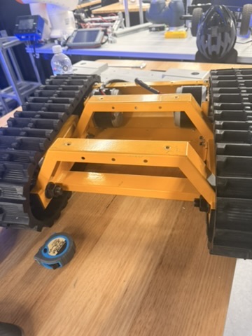
I worked with teammates on fabrication and assembly, including cutting, drilling and fitting parts. This project introduced me to the vertical bandsaw, cold saw, linisher, drill press and other workshop tools. I designed parts for lathe and mill operations and learned their constraints, although I have not yet personally operated those machines or CNC equipment on this project.
Testing revealed the real constraints
The waypoint demonstration showed that the rover can follow a programmed GPS loop while towing a trailer. It did not settle how well the same commands will work on mud or other low-traction ground. The current control assumptions are tuned around grass; a slip-aware approach using the rover’s inertial sensing is one direction we want to investigate.
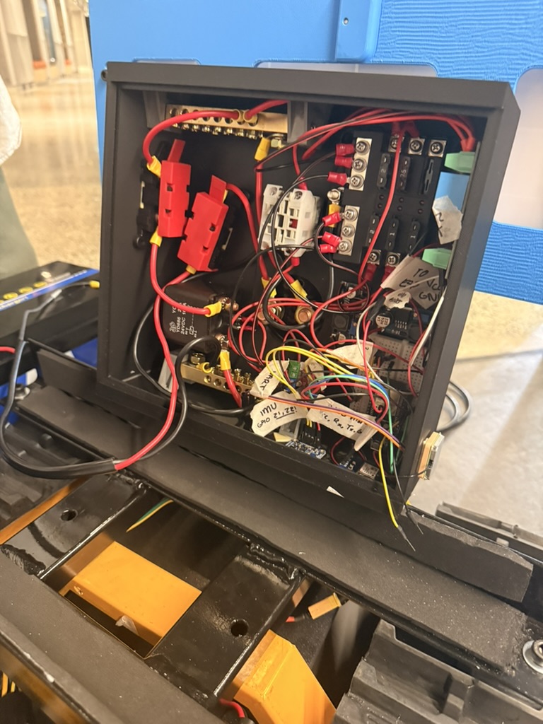
Integration tests also exposed a thermal mistake. During reassembly, a motor-controller heatsink was inadvertently left off. A subsequent test produced local melting where the MOSFETs contacted the plastic enclosure. It was a reminder that an electrical component’s mechanical assembly is part of its operating requirements, especially inside a compact enclosure.
Working with industry
We didn’t design GRAZE in isolation. Over the project we met with several industry partners, including KUKA, Optiway and Woolworths Agriculture, and put our design in front of people who build and buy this kind of equipment. Their feedback changed the design: it pointed out where our assumptions were weak and helped us understand what the market actually needs from a machine like this.
We also visited KUKA on site to see how their autonomous mobile robots (AMRs) combine camera and lidar data to make decisions. That visit gave us a practical direction for our own sensing: how to retune our RealSense cameras so they keep working under the vibration a tracked rover produces on rough ground.
What I learned
GRAZE changed how I design for manufacture. I now check the tool, stock, cost, assembly sequence and service access alongside the nominal shape of a part. Reconstructing the chassis and iterating the enclosures also taught me to treat measured hardware as the source of truth when documentation is missing.
More than anything, testing gave me a better response to failure. A part that catches during installation, a cracked mount or an overheated enclosure gives specific information about the next revision. I want those failure modes to appear during controlled testing, while there is still time to fix them.
Next questions
The next mechanical and control challenge is consistent towing and turning as ground conditions change. Beyond the current proof of concept, the team is considering richer sensing that could give farmers information about livestock and pasture. Those ideas are future work; the immediate priority is a reliable rover and a well-understood set of operating limits.